In view of the difficulties existing in the processing of end-face oil grooves of rolling mill roller bearings, corresponding fixtures and tools were designed to successfully complete the processing task.
Keywords: rolling mill roller bearing; oil groove; equalizing plate; positioning
Introduction
Rolling mill roller bearings have linear contact between the rollers and the raceways, have large radial load-bearing capacity, and are suitable for withstanding heavy loads and impact loads. The friction coefficient is small, suitable for high-speed rotation, and the limit speed is close to that of deep groove ball bearings. The bearing can move axially, can adapt to changes in the relative position of the shaft and the housing caused by thermal expansion or installation errors, and can be used as a free end support. The machining accuracy of the shaft or seat hole is high, and the relative deflection of the outer ring axis after the bearing is installed must be strictly controlled to avoid contact stress concentration. The inner or outer ring can be separated for easy installation and removal.
Processing situation analysis
The new products 313822 and 313824 bearing jackets have completed the turning process in other units. The outer diameter of this product is φ330mm and φ390mm, and the weight of each piece is about 19kg. It requires a milling machine to process 8 equal parts of R75mm oil grooves on both end faces. The oil tank has high precision requirements. The shape and position tolerances such as size, bisection accuracy, and symmetry are required to be within 0.05mm. The smoothness reaches Ra1.6. The processing is difficult. Such products have never been processed before. The dimensions of the outer ring of the 313822 bearing are shown in Figure 1.
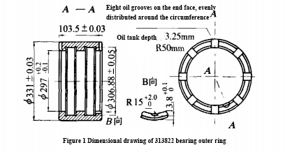
When processing the test piece, an index plate is used for clamping, and a 150 three-sided edge milling cutter is used to process the arc surface. Due to the high resistance of the milling cutter, there is a gap in the indexing plate, the brightness is not good, and it is easy to get stuck, resulting in waste products. In addition, the processing efficiency is low, and the production progress cannot be guaranteed. In response to this situation, we developed our own fixtures and cutting tools, and successively designed the dividing plate (as shown in Figure 2), positioning plate, positioning block, screws, pressure plate, positioning pin, etc., and successfully completed the processing of this type of product.
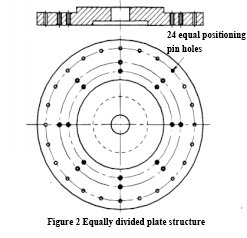
Clamping and positioning when processing the jacket oil tank
After the fixture processing is completed, first draw the circumference and cross lines on the bearing jacket and install it on the equal portion plate. This clamp is self-centering, is not easy to pinch the workpiece, and is clamped firmly. Only one product line needs to be drawn for a batch of products, which reduces the line drawing process, saves handling time, reduces labor intensity, and solves the problems of clamping and dividing. The fixture for processing the first surface of the oil tank is shown in Figure 3.
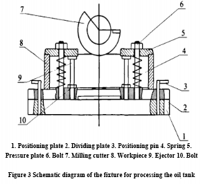
Turning method
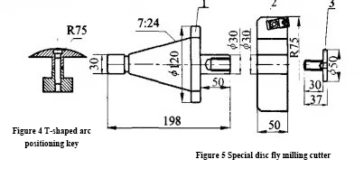
After using the jig to process the 8-equal oil groove on one side, you need to process the 8-equal oil groove on the other end. To this end, a positioning device for turning over is designed to solve the problem of positional symmetry on both sides. A T-shaped arc surface positioning key corresponding to the R75mm oil groove was designed and manufactured, as shown in Figure 4, and was embedded in the T-shaped groove of the bed surface. The arc surface of the positioning block is used to cooperate with the oil groove on the machined surface to determine the symmetrical relationship between the two surfaces. In terms of position, the processing position of the workpiece on the machine tool is determined using the pressure plate fixed on the bed surface and the crosshairs on the workpiece. Using this method, 60 to 80 products can be processed every day.
Tool manufacturing
If you want to process products quickly and with good quality, you need to work hard on the tools and tool feed, as shown in Figure 5. The original three-sided edge milling cutter made of tool steel is now used to transform the flying disc rotary milling cutter using YTl416×16 alloy blades. This knife is highly durable and reduces the number of inspections and measurements. When the flying disc rotary milling cutter is processed on the X61W equipment, the rotation speed is 600r/min and the feed rate is 680mm/min. 60-80 products per side are processed every day, which greatly improves production efficiency.
Conclusion
Through the design of fixtures and cutting tools, the processing of the end face oil groove of the rolling mill roller bearing was successfully completed. The dimensional accuracy, geometry, and positional accuracy met the requirements. The processing efficiency was about ten times higher than that of the dial clamping process, laying a solid foundation for processing such products.