In response to the fracture accident of the cage of the four-row tapered roller bearing in the roll neck of the vertical roller mill of a rolling plate factory, a finite element model of the bearing system was established; the contact unit was used to establish a surface-to-surface contact pair at the important contact positions between the bearing elements. The simulation obtained the deformation and stress distribution of the cage, found out the reasons for the fracture of the bearing cage, and put forward suggestions for improvement in the design of such bearings in the future.
Keywords: four-row tapered roller bearings; vertical roller mill; cage; finite element; pulsating stress
Bearings are important supporting parts that bear loads in various machines and are often called the “joints” of machinery. Rolling mill bearings must meet many requirements such as high speed, heavy load, large impact and harsh environment.
The four-row tapered roller bearing used in the roll neck bearing of a cantilevered vertical roller mill in a certain rolling mill had its cage broken several times in a row (see Figure 1), causing the entire production line to stop production, causing serious losses. This article conducts finite element calculations on the bearing system, focusing on analyzing the deformation and stress of the cage.
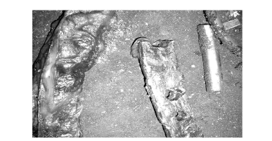
Figure 1 Fracture of roll neck bearing cage of vertical roller mill
Establishment of finite element model
The bearings used in the vertical roller mill of this plant are non-standard four-row tapered roller bearings, which are composed of two double-row tapered roller bearings. Its basic structure is shown in Figure 2: It consists of two double raceway outer rings, four single raceway inner rings, rollers, isolation rings, pins and cages.
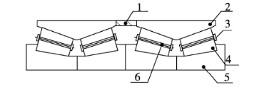
1-Isolation ring; 2-Outer ring; 3-Cage; 4-Roller; 5-Inner ring; 6-Pin shaft
Figure 2 Structural diagram of four-row tapered roller bearings
Four-row tapered roller bearings can bear combined radial and axial loads. Taking into account the symmetry of the bearing structure and the distribution of the load carried by the bearing (the radial load is cosine distributed within 120° along the circumferential direction and evenly distributed along the axial direction). This article takes half of the bearing structure for analysis, as shown in Figure 3.
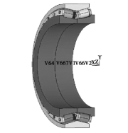
Figure 3 Bearing finite element model
Mesh division and connection method between bearing elements
Mesh division
Three-dimensional solid elements are selected and meshed in the form of volume sweep (Sweep). Volume sweeping can not only obtain more regular hexahedral elements, but also control the node distribution at the contact positions of different parts. This prepares the next step for merging nodes for certain bearing elements.
Connection method between bearing components
Contact units are used to establish surface-to-surface contact pairs between the rolling elements and raceways, between the big ends of the rollers and the inner ring ribs, and between the pins and cages in the radial load area (60°). The nodes between the pin and the rolling element and between the pin and the cage outside the radial load area are processed by node merging.
Loads and constraints
Load
Figure 4 shows the force diagram of the shaft. Where Fr is the radial force at the four-row tapered roller bearing studied, taking Fr=2000kN; the tangent value of the angle between the roll surface and the axis tanα=0.0417; the diameter of the roll at the center of the slab D=860.416mm; spacing L1=1052.5mm, L2=1697.5mm.
Taking the moment on the left end is:
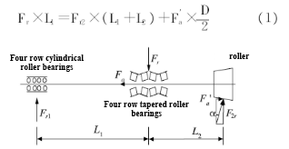
Figure 4 Force diagram of the shaft
Axial load balance is:
F,a=Fa
The load relationship at the roll is:
F,a=Fe×tanα
Combine the above three equations to obtain the axial load of the bearing Fa=2.73kN.
During finite element analysis, the axial load is applied at the contact point between the bearing and the shaft shoulder; the radial load is applied within 60° of the surface of the inner ring of the bearing, with a cosine distribution along the circumferential direction and a uniform distribution along the axial direction.
Constraints
According to the installation form and loading conditions of the bearing, the boundary conditions are as follows:
Nodes on the outer surface of the outer ring: radial displacement constraint Ux=0 and circumferential displacement constraint Uy=0;
Node on the right side of the outer ring: axial displacement is approximately Uz=0;
Symmetry constraint: Node SYMM=0 on the symmetric surface.
The effect after bearing loading and restraint is shown in Figure 5.
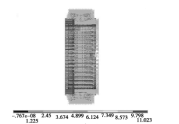
a)Front view

b)Side view
Figure 5 Load and constraint effect diagram
Analysis of finite element calculation results
Deformation of cage
Affected by the bending deformation of the shaft, the axial displacement of the cage should be opposite up and down. As shown in Figure 6, take a section I parallel to the bearing end face at half the width of the bearing. It can be seen from the positive and negative of the cage displacement values that the upper ends of all cages (bearing load areas) are away from section I, while the lower ends of the cages (bearing non-load areas) are close to section I. This shows that the cage is tilted relative to section I.
Likewise, the radial displacement of the cage is not the same up and down. Therefore, especially under high-speed and heavy-load conditions, the deformation of the cage has a great impact on the stability of the entire bearing.
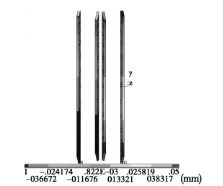
Figure 6 Axial deformation of cage
Stress distribution of cage
Figures 7 to 9 are respectively the first principal stress cloud diagram, the third principal stress cloud diagram and the equivalent stress cloud diagram of the cage.
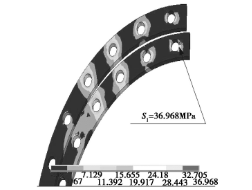
Figure 7 The first principal stress cloud diagram of the cage
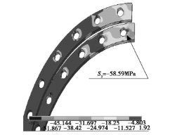
Figure 8 The third principal stress cloud diagram of the cage
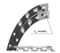
Figure 9 Equivalent stress cloud diagram of cage
It can be seen from the above figures that the area around the pockets of the cage is a stress concentration area. The first principal stress S1 = 36.968MPa and the third principal stress S3 = -58.59MPa at the maximum stress position. It can be seen that the stress state here is both tension and compression, and the equivalent stress should be used to check its strength. Its equivalent stress Seqv=84.6MPa. When the bearing rotates 180°, the equivalent stress there is basically 0, so the cage is subject to pulsating cyclic stress with cyclic characteristic r=0. Due to the large impact load of the vertical roller mill of this plant, the cage pockets were subjected to great pulse cyclic stress, and the cage broke at the pockets due to fatigue.
Conclusion
1) In the past, the cage was considered to be an unstressed part that only rotates around the bearing axis. However, through the calculation and analysis in this article, it can be seen that the cage will be deformed and affected by cyclic stress due to the deformation of the shaft and the impact of the rollers.
2) When designing bearings in the future, the bearing cage should be ensured to have sufficient strength.