This article explains how to choose rolling mill bearings.
Keywords: rolling mill bearings; selection
Size selection
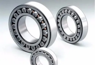
Selection of geometric parameters of bearings. In most bearing applications, the given load and speed are the main basis for selecting bearings. However, when initially selecting a suitable bearing to match the roll, you need to consider the type of rolling mill, the maximum diameter of the roll body Dmax and The minimum diameter Dmin, the diameter d and length L of the roll diameter, the pressing screw distance A, the wall thickness of the bearing seat and other factors. In rolling mills, four-row cylindrical bearings or four-row tapered bearings are generally used. Firstly, it is determined that the outer dimension of the bearing seat between the rolls cannot be larger than the minimum roll diameter Dmin. Secondly, the value of the roll diameter is: d=(0.50~0.55)Dmax, L= (0.83~1.0)d, which limits the gap between the bearing seat and the roller diameter. The minimum cross-section of the bearing seat and the bearing size must be balanced within this gap.
In many cases, the bore size of the bearing has been specifically defined by the structure of the machine or device. Regardless of whether the working life, static load safety factor and economy meet the requirements, size calculations must be carried out before the final selection of the remaining dimensions and structural forms of the bearing. The calculation involves comparing the actual load on the bearing to its load capacity. The static load of a rolling bearing means that the bearing is stationary after loading (no relative movement between the inner and outer rings) or the rotation speed is very low. In this case, calculate the safety factor for excessive plastic deformation of the raceway and rolling elements. Most bearings are subject to dynamic loads, and the inner and outer rings move relative to each other. Dimensional calculations check the safety factor of early fatigue damage of raceways and rolling elements. Only in special cases is the nominal life calculated according to DIN ISO 281 for the actual achievable operating life. For designs that focus on economic performance, it is necessary to make full use of the bearing’s load-bearing capacity as much as possible. In order to make full use of the bearing, the accuracy of the calculation of bearing size selection is more important.
Static load bearings
Calculating the static load safety factor Fs helps determine whether the selected bearing has sufficient static load rating. FS =CO/PO where FS static load safety factor, CO rated static load [KN], PO equivalent static load [KN] Static load safety factor FS is the safety factor to prevent permanent deformation in the contact area of rolling parts. For bearings that must run smoothly and have extremely low noise, a high FS value is required; where only moderate running noise is required, a smaller FS can be selected; the following values are generally recommended: FS=1.5~2.5 is suitable for low noise level FS =1.0~1.5 is suitable for normal noise level FS=0.7~1.0 is suitable for medium noise level Rated static load CO [KN] is listed in the table for each type of bearing. The theoretical pressure generated by this load (radial force for radial bearings and axial force for thrust bearings) at the center of the contact area between rolling elements and raceways is: -4600 N/MM2 Self-aligning Ball bearings – 4200 N/MM2 Other types of ball bearings – 4000 N/MM2 Under the action of the rated static load CO, the total plastic deformation produced by all roller bearings at the maximum load-bearing part of the contact area between the rolling element and the raceway is approximately It is one ten thousandth of the rolling element diameter. The equivalent static load PO [KN] is a theoretical value, which is the radial force for radial bearings and the axial and centripetal forces for thrust bearings. The stress generated by PO in the center of the maximum load-bearing contact area of the rolling elements and raceways is the same as the stress generated by the actual load combination. PO=XO*F r+Ys*Fa[KN] Among them, PO equivalent static load, Fr radial load, Fa axial load, the units are all kilonewtons, XO radial coefficient, YO axial coefficient.
Dynamic load bearing
The standard method for calculating dynamically loaded bearings specified in DIN ISO 281 is based on material fatigue failure (pitting). The life calculation formula is: L10=L=(C/P)P [106 turns] where L10=L nominal rated life [106 revolutions] C Rated dynamic load [KN] P Equivalent dynamic load [KN] P Life index L10 is the nominal rated life in units of 1 million revolutions [106 revolutions] C Rated dynamic load [KN] P Life index L10 is in Nominal rated life converted into units of 1 million. For a large group of bearings of the same type, 90% should meet or exceed this value. The rated dynamic load C [KN] can be found in the parameter table of each type of bearing. Under this load, the bearing can achieve a rated life of 1 million revolutions. The equivalent dynamic load P [KN] is a theoretical value, which is the radial force for radial bearings and the axial force for thrust bearings. Its direction and size are constant. The bearing life under equivalent dynamic load is the same as that under actual load combination. P=X*Fr+Y*Fa Among them: P equivalent dynamic load, Fr radial load, Fa axial load, the units are all kilonewtons, X radial coefficient, Y axial coefficient. The calculation basis for the X, Y values and equivalent dynamic loads of different types of bearings can be found in the tables and prefaces of each type of bearings. The life index P of ball bearings and roller bearings is different. For ball bearings, P=3. For roller bearings, P=10/3.
Variable load and variable speed
If the value and speed of the bearing’s dynamic load changes with time, then corresponding considerations must be taken when calculating the equivalent load. Continuous load and speed curves are replaced by piecewise approximations.
Minimum load of rolling bearings
Too small a load coupled with insufficient lubrication will cause the rolling elements to slip and cause bearing damage. The minimum load coefficient of cage bearings is P/C=0.02, while the minimum load coefficient of full complement bearings is P/C=0.04 (P is equivalent dynamic load, C is rated dynamic load).
Based on the above aspects, try to choose bearings with national standard sizes and models. It should be because all major bearing manufacturers have technical samples for their products and have their own data basis for the bearing load and rotation speed.
Bearing fit
The selection of rolling mill bearing fit should be determined based on factors such as bearing type and size, load nature and size, and ease of assembly and disassembly. The correct selection of bearing coordination should ensure the normal operation of the bearing and prevent relative rotation between the inner ring and the shaft, and the outer ring and the seat hole during operation. For rolling mill bearings that bear radial load, when the speed is higher, the load is greater, and the impact is stronger, the tighter fit with the shaft should be selected, while for bearings that are frequently replaced, a loose fit is generally selected; for bearings that bear axial load Rolling mill bearings should choose a transition fit or a loose fit with the shaft. In order to avoid bearing radial loads, a large gap is usually left between the bearing outer ring and the seat hole.
When selecting bearing fits, the following factors should be considered:
Type of load
According to the rotation of the synthetic radial load vector acting on the bearing relative to the ferrule, the load borne by the ferrule can be divided into: fixed load, rotational load and swing load.
(1) The resultant radial load caused by fixed load acting on the ring is borne by the local area of the ring raceway and transmitted to the relatively local area of the shaft or bearing seat. This load is called fixed load.
The characteristic of a fixed load is that the resultant radial load vector is relatively stationary to the ferrule. Ferrules that bear fixed loads generally have a looser fit.
(2) The resultant radial load vector caused by the rotary load acting on the sleeve rotates along the circumferential direction of the raceway and is borne by each part of the raceway in turn. This load is called rotary load, also called cyclic load. . The characteristic of rotary load is that the resultant radial load vector rotates relative to the ferrule. Transition or interference fit should be used between the ferrule and the shaft or housing hole that bear the rotational load. If installed with a clearance fit, slipping will occur between the bearing sleeve and the shaft or housing hole, resulting in wear of the contact surface, and frictional heating, which will cause the temperature to rise sharply and the bearing to be damaged quickly. The size of the fit interference depends on the operating conditions. The principle is that when the bearing is operating under load, the ferrule does not “crawl” on the mating surface on the shaft or in the housing hole.
(3) The synthetic radial load vector of the swing load acting on the ring swings relatively within a certain area of the ring raceway and is borne by a certain area of the raceway, or the load acting on the bearing is an impact load or vibration load. If its direction or value changes frequently, this kind of load is called a swing load, also known as an indefinite load.
When the bearing is subjected to swing load, especially when it is subjected to heavy load, both the inner and outer rings should adopt an interference fit. When the inner ring rotates, the inner ring usually adopts a fit under rotational load. However, sometimes when the outer ring must move axially in the bearing box or the load is light, a slightly looser fit than that under rotational load can be used.
Load size
The bearing ring is compressed in the radial direction under the action of the radial component of the load, which will cause the mating surface to relax. Under heavy rotational loads, slipping may easily occur. Therefore, for heavy load applications, the fit should generally be tighter than for light load and normal load applications. The heavier the load, the greater the fit interference should be.
Bearing size
As the size of the bearing increases, the greater the interference fit selected, the greater the clearance fit.
Bearing clearance
The use of interference fit will lead to the reduction of bearing clearance. It should be checked whether the bearing clearance meets the usage requirements after installation, so as to correctly select the fit and bearing clearance.
Working temperature
When the bearing is running, the temperature of the ferrule is usually higher than that of adjacent parts. The inner ring of the bearing may become loose with the shaft due to thermal expansion, and the outer ring may affect the axial movement of the bearing due to thermal expansion. Therefore, when choosing a fit, care must be taken to consider the temperature difference and the direction of heat conduction.
Bearing rotation accuracy
When the requirements for bearing rotation accuracy and smooth operation are high, in order to eliminate the effects of elastic deformation and vibration, try to avoid using clearance fit.
Structural design and materials of shaft and bearing seat
If the surface shape of the shaft or bearing seat is irregular, it will cause abnormal deformation of the inner and outer rings of the bearing and uneven stress. For split bearing seats, interference fit should not be used with the bearing outer ring, but the outer ring should not be allowed to rotate in the bearing seat hole. When the bearing is installed on a thin-walled, light alloy bearing seat or hollow shaft, in order to ensure that the bearing has sufficient supporting surface, a tighter fit than that selected on a thick-walled bearing seat, cast iron bearing seat or solid shaft should be used.
Convenience of installation and disassembly
In many applications, clearance fits are required to facilitate installation and removal. Depending on the operating conditions, if interference fit installation is necessary, separate bearings (cylindrical roller bearings, needle roller bearings, tapered roller bearings and thrust bearings in which the inner and outer rings can be installed separately) or bearings with tapered inner holes should be used , making loading and unloading easy.
Axial displacement of non-fixed end bearings
Bearings installed at the non-fixed end require a ring of the bearing to have a certain amount of movement in the axial direction. Usually, the ring bearing a fixed load (usually the outer ring) is installed with a clearance fit. If a cylindrical roller bearing with an inner or outer ring without ribs is used to install it at the non-fixed end, both the inner and outer rings can be installed with an interference fit.
Clearance selection
The clearance of the bearing refers to the amount of movement of one ring when one ring is fixed and the other ring moves from one extreme position to the other relative to the fixed ring under no load. Those that move radially are called radial clearance, and those that move axially are called axial clearance.
Usually, the original radial clearance of the bearing is larger than the clearance when the bearing is working. The radial clearance of the bearing has a great impact on the life, temperature rise and noise of the bearing. When determining bearing radial clearance, the following points must be considered:
(1) When installing with an interference fit, the expansion of the inner ring and the contraction of the outer ring lead to a reduction in clearance.
(2) At operating temperature, the temperature difference between the inner and outer rings of the bearing and the thermal expansion of related parts lead to changes in clearance.
(3) When working, ball bearings are usually at operating temperature and the clearance should be close to zero. For roller bearings, under normal working conditions, a certain radial clearance should usually be left.
Bearing material selection
The performance and reliability of rolling bearings depend largely on the materials from which the bearing parts are made.
When a rolling bearing rotates at high speed under load, the contact parts of the ring raceway and rolling elements repeatedly bear large contact stress. Long-term operation is prone to fatigue spalling of materials, resulting in bearing damage. Therefore, the materials of rolling bearing rings and rolling elements must have It has the advantages of high hardness, strong fatigue resistance, wear resistance, and good dimensional stability.
Materials of ferrules and rolling elements
Rings and rolling elements are usually made of high carbon chromium bearing steel. Most bearings use GCr15, and for bearing rings with larger cross-sections and rolling elements with larger diameters, GCr15SiMn with good hardenability is used. High carbon chromium bearing steel is integrally hardened steel, and its surface and core can be hardened, making it the best material for rolling bearings.
Due to different use occasions, some bearings require materials with special properties, such as impact resistance, high temperature resistance, corrosion resistance, etc.
Carburized steel is usually used for the rings and rolling elements of bearings that bear impact loads during operation or large and extra-large bearings. Carburizing bearing steel is carburized within an appropriate depth range on the surface of chromium-molybdenum steel, chromium-nickel-molybdenum steel and other materials, so that it has a dense structure and forms a hardened layer, while the center part has a lower hardness and a better core Impact toughness, due to the good performance of carburized bearing steel, its calculated life is the same as that of high carbon chromium bearing steel. Bearings working under high temperature are made of high-temperature bearing steel with good heat resistance.
Bearings that come into contact with corrosive media during work are made of stainless bearing steel.
It is worth noting the cleanliness of the bearing steel. The higher the cleanliness, the fewer non-metallic inclusions, the lower the oxygen content, and the longer the bearing fatigue life. Vacuum degassing steel or vacuum remelted steel can meet this requirement. Bearings requiring high reliability should be made of electroslag remelted steel.
Material of cage
The cage has a great influence on the performance and life of the rolling bearing, and the selection of its material is particularly important. The cage material should have the characteristics of high mechanical strength, good wear resistance, impact load resistance and dimensional stability.
Cages are generally divided into stamped cages and solid cages.
The cage is mainly used to isolate the rolling elements to prevent contact and friction between them. For separable bearings, it can also be used to keep the rolling elements from falling off to facilitate disassembly and installation. During grease lubrication, the cage can also play the role of storing grease to improve bearing lubrication.
The structure of the cage varies greatly depending on the type and size of the bearing. These differences are mainly reflected in cage structure, shape, materials, manufacturing methods, production costs, etc. According to the different process characteristics of the cage, the main materials used are: various stamped cages mostly use 10 steel plates and brass plates, and the materials for machined solid cages are mostly steel 30, brass HPb59-1, bronze QAL10-3-1.5, Aluminum ZL102 and phenolic laminated cloth pipes, etc., in addition to powder metallurgy and nylon 66, etc.
Each type of bearing of different sizes specifies a cage structure that is the standard structure for this type of bearing. Except for standard structural cages, which are not represented in the bearing code, cages using non-standard structural types should be represented by the suffix code specified in the code section of this catalog. However, if one of the following conditions is met, the cage material change code will not be compiled.
(1) When the outer diameter of the bearing D ≤ 400mm, the stamped cage of steel plate strip and brass plate is used; when the outer diameter of the bearing D ≥ 400mm, the deep groove ball bearing and single row cylindrical roller bearing with brass solid cage are used;
(2) Double-row cylindrical roller bearings and asymmetric spherical roller bearings with brass solid cages;
(3) Bearing outer diameter D≤200mm, using steel plate with stamped cage, D>200mm, using brass solid cage self-aligning ball bearings;
(4) It adopts the symmetrical roller type of spherical roller with steel plate and stamped cage and with movable middle retaining ring;
(5) Double row angular contact ball bearings, thrust needle roller bearings and long cylindrical roller bearings;
(6) Cage needle roller bearings using steel plate strips or hard aluminum plate strips with stamped cages;
(7) Separate single row angular contact ball bearings with steel plate strips and copper plate strips stamped cages;
(8) Use aluminum solid cage double half inner ring or double half outer ring three-point or four-point contact single row angular contact ball bearings;
(9) The contact angle α = 40° for the bearing outer diameter D ≤ 250 mm, the steel plate stamping cage is used, the contact angle a = 15°, 25° uses the phenolic laminated cloth tube solid cage, and the D > 250 mm uses brass Or single row angular contact ball bearings with duralumin solid cage;
(10) P5, P4, P2 class single row angular contact ball bearings with phenolic laminated fabric controlled solid cages and single row angular contact ball bearings with locks in the inner ring and their modified structures;
(11) Double inner ring double row angular contact ball bearings and thrust roller cylindrical conical and spherical roller bearings using solid cages;
(12) Tapered roller bearings with outer diameter D≤650mm adopt steel plate stamping cages and bearings with outer diameter D>650mm adopt steel solid pillar cages;
(13) Thrust ball bearings with outer diameter D≤250mm adopt steel plates with stamped cages and bearings with outer diameter D>250mm adopt solid cages.