When the rolling mill rolls are supported by four-row cylindrical roller bearings, their structure is mainly determined based on the JB/T5389.11995 standard. During long-term use, it was found that the cage of the bearing was easily deformed during the assembly of the finished product, causing premature failure of the bearing during operation. Therefore, taking the FC5274220 bearing as an example, the following improvements have been made to its structure.
Keywords: four-row cylindrical roller bearing; structure
Disadvantages of the original bearing structure
The original bearing uses a brass comb-shaped cage, and a gap for filling the roller is machined on one side of the outer ring. When assembling the finished product, a row of rollers needs to be loaded into the cage from the filling gap. In order to ensure that the rollers do not fall out of the filling gap during normal operation of the bearing, the minimum height of the filling gap relative to the raceway must be limited. Therefore, when installing the roller, it must be tilted at a certain angle and then driven in hard, rather than directly put in, as shown in Figure 1. This causes the cage’s lintels and pockets to deform and tilt toward the center of the bearing.
The consequences are: (1) The roller head will sag, causing the inner circle size of the bearing to change, making it more difficult to install the bearing on site. When using robots for automatic assembly, the drooping roller heads can easily scratch the inner ring raceway and reduce the service life of the bearing. (2) The gap between the pockets of the rollers and the cage is uneven, so that the cage cannot guide the rollers accurately, the rollers become more skewed, the bearing wear accelerates, the operation deteriorates, and the damage of the cage leads to the failure of the entire bearing. This is one of the main forms of damage to rolling mill bearings. (3) Since the hardness of the roller is higher than that of the outer ring, the outer ring raceway is easily scratched when the roller is installed, causing hidden dangers to the normal operation of the bearing.
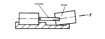
Figure 1 Schematic diagram of roller installation into cage
Features after structural improvement
In view of the shortcomings of the original bearing structure, after repeated research and demonstration, a single-pocket brass solid cage was used to replace the original comb cage. The outer ring eliminates the mid-range edge and filling gap, and arranges two rows of rollers side by side. In order to increase the strength of the cage and improve the process performance, in addition to reducing one pocket, a new process of screw fastening and industrial special adhesive to prevent loosening is used to replace the rivet riveting process used in the original physical cage, as shown in Figure 2. . This not only solves the problem of difficulty in processing rivet holes due to the excessive length of the cage lintel, but also fully guarantees the rigidity of the cage. The advantages are:
(1) The problem of cage deformation caused by the rigid assembly of rollers is eliminated from the structure, and the geometric accuracy of cage processing is organically combined with the overall performance of the bearing. The structural defects such as roller head sagging, skewing and raceway scratches caused by bearing assembly can be completely avoided, and the operational reliability of the bearing is greatly enhanced. (2) After the middle rib is removed from the outer ring, the effective length of the roller increases, which increases the basic dynamic load rating of the bearing from 1700kN to 1900kN. When the load is the same, that is, the equivalent dynamic load remains unchanged, the basic rating life of the improved bearing is increased by 45% compared with that before the improvement.
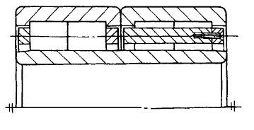
Figure 2 Improved bearing structure