The four-row tapered roller bearings of the work rolls of the 3500mm medium-thick plate four-high rolling mill bear both radial and axial forces. Its working condition is to withstand the over-balanced force of the upper roll system, or the roll bending force when flatness control is required, as well as the axial force on the work roll. Conduct rod system analysis on the work roll system mechanism to determine the constraints of the bearing operation. A trapezoidal plate unit is developed to simulate the tapered roller and is fixed on the inner ring. The outer ring and inner ring are respectively attached to the bearing seat and the roll neck. The multi-object contact rolling bearing is simplified into a three-dimensional elastic friction contact problem of two objects. And improvements were made based on the characteristics of tapered roller bearings that can bear both radial load and axial load.
Keywords: rod system analysis; tapered roller; boundary element method; trapezoidal plate element; three-dimensional load
Introduction
Four-row tapered roller bearings for the work rolls of the 3500mm medium-thick plate four-high rolling mill. Bears radial force and axial force at the same time. Its working condition is to withstand the over-balanced force of the upper roll system, or the roll bending force when flatness control is required, as well as the axial force on the work roll. Tapered bearings have been strictly selected according to existing rolling mill design theories, but short-life burnout has long plagued the safe operation of rolling mills. Currently, among large-scale rolling mill equipment accidents in Japan, the short-life burnout accident rate of bearings is second only to rolls. Since the mid-1980s, the experimental and load characteristic analysis research of large four-row tapered bearings has been a hot topic paid attention to by industry technology and academia.
The life evaluation of four-row rolling bearings in rolling mills is based on the load characteristics of each row of rollers. However, the elastic bending deformation of the rolling mill rolls and the statically indeterminate micro-scale runaway behavior of the gap bearing seat positioning in the frame window directly destroy the load sharing characteristics of the rolling bearing. Three-dimensional analysis of the load characteristics of four-row tapered bearings is difficult. So far, there are only Monte Carlo random simulation methods and three-dimensional finite element methods. However, the above two solutions do not consider the axial force and the different constraints of the bearing seat, thus losing the influence of the structural characteristics of the tapered bearing and the environment of the rolling mill mechanism.
The mechanism of the rolling mill roll system was analyzed, the working constraint environmental conditions of the bearings were summarized, and the plate unit was given to simulate the three-dimensional elastic contact boundary element method of the rollers. It is suitable for the three-dimensional load analysis of four-row short cylindrical roller bearings and double-row angular contact ball bearings under rolling force, horizontal force, axial force and their combined working conditions. On this basis, a trapezoidal elastic plate unit was developed to simulate the tapered rollers and calculate the three-dimensional load of the four-row tapered bearings of the 3500mm medium-thick plate four-high rolling mill.
Rolling mill roll system and bearings
Mobility of work roll system
The upper work roll system consists of work rolls, four-row tapered bearings, bearing seats, balance roll bending devices and axial fixed baffles, and is subject to the geometric constraints of the back-up rollers and their bearing seat windows. When the lateral gap between the bearing seat and the support roller window is ignored, the roller system is abstracted into a plane rod system in order to analyze the micro-scale behavior of the roller system in the direction of the balancing force or roll bending force, as shown in Figure 1.
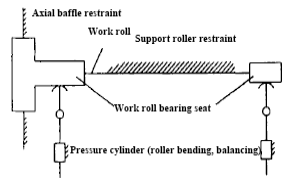
Figure 1 Work roll tie system
Under the constraint of the back-up roller on the work roll, the control side and the driving side of the work roll are separated into two independent groups of rod systems. Therefore, micro-scale mobility analysis is conducted specifically on the control side rod system. When the clamping cylinder only applies balancing force, the partial planar rod system on the control side of the work roll is a 2-rod, 3-low-pair and 1-high-pair rod system, as shown in Figure 2.
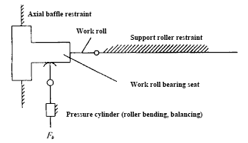
Figure 2 Work roll system control side rod system
From the mobility formula (number of rods n, number of high motion pairs m1, number of low motion pairs m2):
F=3n-2 m2- m1 (1)
The degree of activity of the rod system is:
F=2×3-3×2-1×1=-1
The roller system is a statically indeterminate mechanism.
When a roll bending force larger than the balance force is applied, the bending deflection of the work roll neck and the bearing seat is approximately simulated as a system of 3 rods, 4 low pairs and 1 high pair with virtual hinges. At this time, the activity of the roller system is:
F=3×3-4×2-1×1=0
The control side bearing seat has no mobility, that is, it cannot self-position.
Bearing specifications and loads
The parameters of four-row tapered bearings are shown in Table 1.
Table 1 Bearing specifications and loads
| Inner diameter/mm | Outer diameter/mm | Width/mm | Elastic modulus/GPa | modulus/GPa | Poisson’s ratio Bending force/kN | Axial force/kN |
| 625 | 815 | 480 | 210 | 0.3 | 30~2000 | 100~200 |
The performance parameters of four-row tapered roller bearings are shown in Table 2.
Table 2 Bearing performance parameters
| Rated dynamic load/kN | Rated static load/kN | Speed/r.min-1 | x | y | z |
| 5900 | 12400 | 600 | 1 | 2 | 0.33 |
Boundary element method calculation of three-dimensional load distribution of four-row tapered bearings
Roller, tapered bearing and bearing seat and their assembly grid
For the upper roller system, take 1/2 part (control side) as the calculation model. The bearing seat equipped with four rows of tapered bearings is connected to the frame through axial fixed baffles and balance system beams, and is therefore subject to geometric constraints (ie, rigid supports). The tapered roller is simulated as a trapezoidal plate unit and is fixed on the inner ring of the bearing. The inner ring is fixed on the roll neck and integrated into one. The outer ring of the bearing is fixed on the bore of the bearing seat and integrated into one. The discrete mesh of the roll and bearing seat is shown in Figure 3a) and b), and its assembly model is shown in Figure 3c).
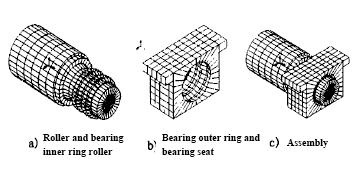
Figure 3 Discrete mesh and assembly model
The roller part is divided into 810 nodes and 812 four-node linear elements; the bearing seat part is divided into 564 nodes and 564 four-node linear elements; and there are 240 contact point pairs.
Three-dimensional distribution of load on each row of bearing rollers during rolling
The load distribution characteristics of the bearing seat without self-positioning (that is, without swinging) are quantitatively given, as shown in Figure 4.
1) No axial force (bending roller or balancing force 500kN)
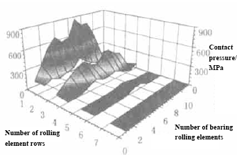
Figure 4 Three-dimensional distribution of contact pressure in each row of bearings
In order to evaluate the roll bending ability of the four-row tapered bearing, the bearing load characteristics under the conditions of self-positioning (i.e. swing) of the bearing seat and control of no axial force are given, as shown in Figures 5 and 6.
2) No axial force (bending roller or balancing force 1500kN)
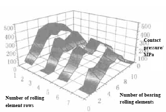
Figure 5 Three-dimensional distribution of contact pressure in each row of bearings
3) Axial force 200kN, towards the control side (bending roller or balancing force 1500kN)
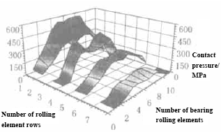
Figure 6 Three-dimensional distribution of contact pressure in each bearing row
Bearing life assessment
Four-row tapered bearings are wide series multi-row bearings. The selection or determination of bearing life is based on the ideal condition that all rows of bearing rollers are evenly loaded. When abnormal eccentric load occurs in a bearing, the usual method of multiplying by a certain eccentric load coefficient (generally less than 1.33) is unrealistic. Because the abnormal eccentric load rate of the bearing far exceeds the allowable eccentric load rate, and the actual life span is determined by the load of a certain row of the bearing. If the rollers in this row fail due to overload, the other intact rollers will be useless and will be scrapped together.
During the rolling process, micro-scale uncontrolled behaviors such as elastic bending deformation of heavy-loaded rolls and roll crossing caused by gap bearing seats cause abnormal eccentric load and axial overload of the bearings. Therefore, it is scientific to quantitatively calculate the load of each row of bearings under the bending force, axial force and micro-scale behavior of the roller system, and make a bearing life assessment.
Bearing life formula
Commonly used life calculation formulas are:

In the formula:
n——rotation speed; C——allowable dynamic load of bearing; P——bearing load.
In order to scientifically evaluate the bearing life, the bearing life is evaluated according to the maximum load of a certain row of rollers, and the average roller load is defined. The average bearing load multiplied by the number of roller rows is equal to the total load of commonly used bearings. Right now

In the formula: pe——average load of roller; I——number of roller rows.
The total load of the four-row tapered roller bearings on the work rolls of the four-high rolling mill is:

In the formula: PR——bearing radial load; PA——bearing axial load; X and Y——are the corresponding dynamic load coefficients respectively.
Rewrite equation (2) into the bearing life LA formula expressed according to the average roller load, that is:

Define the eccentric load coefficient as the ratio of the actual load of the roller to the average load of the roller:

From this, the bearing life formula for roller eccentric load is obtained:

Bearing life assessment
According to the working conditions of whether the bearing seat is self-aligned and whether it is subjected to axial force, and the bearing load distribution ratio obtained in the above Figures 4 to 6 (Figure 7), the bearing life prediction is made, as shown in Table 3.
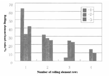
Figure 7 Load distribution ratio of four rows of rollers
Table 3 Bearing life evaluation
| Load status serial number | (1) | (2) | (3) |
| Radial load/kN | 500 | 1500 | 1500 |
| Ideal life/h | 326469 | 8384 | 5524 |
| Unbalanced load coefficient/k | 2.54 | 1.31 | 1.70 |
| Single row (row 1) maximum load ratio/% | 63.6 | 32.8 | 42.0 |
| Bearing life/h | 14601 | 3408 | 924 |
To sum up, the actual working life of the four-row tapered bearing does not solely depend on the life given by the bearing specifications (i.e., the manual), but also depends on the micro-scale behavior of the roller system mechanism and the size of the axial force and its direction of action. . The bearing seat is not self-aligned, causing the bearing load distribution to be obviously uneven; due to the axial force, only three rows of four-row tapered bearings often carry the load. For four-row tapered bearings, especially when the bearing seat is out of position and the axial force acts toward the control side, the unbalanced load of the rollers in each row of the bearing is the most serious. The out-of-control micro-scale behavior of the bearing seat and the effect of axial force can reduce the actual life of the bearing by 22 times.
From the above evaluation, it can be seen that the actual life of the four-row tapered bearing under the action of a general balancing force (500kN) reaches 14600h, far exceeding the 5000h requirement. However, it cannot meet the working life of 5000h without self-alignment and 1500kN roll bending force.
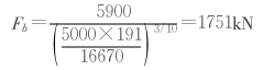
Under the ideal working conditions of self-positioning of the bearing seat and no roll bending force, it is necessary to ensure that the maximum roll bending force corresponding to the roll speed of 191r/min (rolling speed of 10m/s) and the life of 5000h is:
Conclusion
1) The trapezoidal plate element simulates the three-dimensional elastic contact boundary element method of tapered rollers, which is effective in analyzing four-row tapered bearings and has high calculation accuracy. Completing the calculation on a microcomputer takes CPU=80min.
2) The load of the four-row tapered bearing is particularly sensitive to the form of the rolling mill roll bearing seat support and the axial force state. Control of the micro-scale behavior of the rolling mill roll system will determine the load characteristics of the four-row tapered bearings. The four-row tapered bearing has a roll bending capacity of 1750kN with a lifespan of 5000h under the conditions of ensuring the self-positioning of the bearing seat and no roll bending force.
3) On the premise that the structural dimensions of the work roll and bearing seat parts remain unchanged, it is necessary to have a 2MN roll bending capacity that ensures 5000h, and develop a 3-rod, 4-low pair open/closed composite self-aligning bearing seat that can regulate the micro-scale behavior of the roll system.